
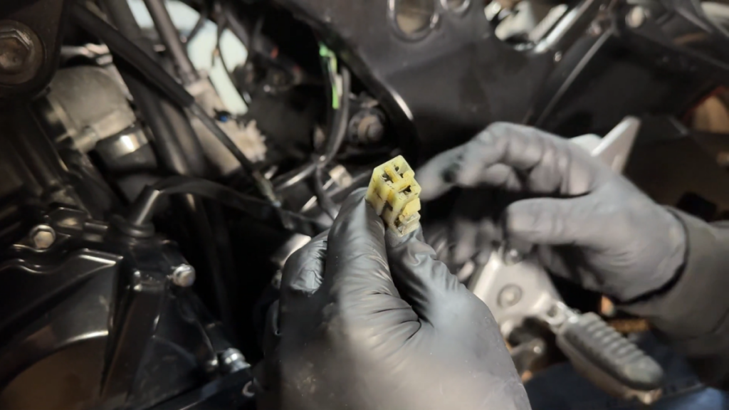
Electrical problems are among the most unpleasant faults for many riders. The reason is simple — electrical current is invisible, and when the charging system stops working properly, tracking down the problem often feels like guesswork.
One of the most common symptoms is the following: you press the starter, but instead of the engine cranking normally, you hear a rapid clicking or buzzing, and the dashboard lights start to flicker and fade out.
Many riders immediately decide the battery is faulty, buy a new one, and a few days later end up with the same problem again.
The reason is that the motorcycle’s electrical system relies on three main components:
- the battery;
- the alternator, or more precisely the stator;
- the regulator/rectifier.
In this article we will look at how the motorcycle generates electricity and how, step by step, to determine where the problem is coming from, using an ordinary digital multimeter.
The Three Main Elements: Battery, Stator, and Regulator/Rectifier
To correctly find an electrical fault, you first need to understand how these three components work together.
1. The battery – stores the electrical energy
The battery’s main job is to store enough energy to power the starter and allow the engine to start.
It also helps stabilize the voltage to the electronic systems and the ECU – the engine control unit.
During normal engine operation, the main electrical supply is provided by the motorcycle’s charging system, while the battery is kept charged.
2. The alternator / stator – the motorcycle’s generator
Once the engine is running, the production of electricity begins.
On most motorcycles, the charging system consists of:
- a stator – stationary copper windings;
- a rotor – a rotating part with magnets.
When the rotor spins around the stator, alternating current – AC – is generated.
The higher the engine RPM, the more voltage the stator produces. At higher RPM it can reach over 60 V AC.
This is the generator of your motorcycle.
3. The regulator/rectifier – controls the voltage
The motorcycle’s electrical system cannot directly use the high AC voltage that comes from the stator.
Most systems work with low-voltage direct current – DC.
That is why the regulator/rectifier has two main jobs:
Rectifying the current
It converts the AC from the stator into DC.
Regulating the voltage
It limits the voltage to safe values, usually around 13.5–14.5 V.
This stabilized voltage powers:
- the headlights;
- the fuel injection;
- the ECU;
- the rest of the electronics;
and at the same time charges the battery.
Diagnosing the Electrical System Step by Step
Before you start buying a battery, regulator, stator, or other expensive parts, do these three basic checks.
You need a standard digital multimeter.
Step 1: Testing the Battery Under Load
1. Set up the multimeter
Select measurement of direct voltage:
DC Voltage – 20 V range
2. Measure the voltage with the engine off
Place the probes on the battery terminals.
On a well-charged 12-volt battery, you should normally see approximately:
12.6–12.8 V
If the value is around 12.0 V or lower, the battery is heavily discharged.
3. Do a load test
Leave the multimeter probes connected to the battery and press the starter.
Watch the voltage at the moment the starter tries to crank the engine.
If the voltage drops below approximately:
10.5 V
the battery most likely can no longer deliver the necessary current under load.
This can indicate damaged or worn cells, and the battery probably needs to be replaced.
Step 2: Checking Whether the Motorcycle Is Charging
The next check shows whether the charging system is working properly.
1. Start the engine
Leave the multimeter connected to the battery terminals.
2. Raise the RPM
Apply throttle to approximately:
4000 RPM
3. Watch the voltage
With a healthy charging system, the voltage should gradually rise and stabilize approximately between:
13.8 and 14.5 V DC
This shows that the charging system is working and the battery is charging.
What do the deviations mean?
If the voltage stays around 12 V or even starts to drop as the RPM increases, the motorcycle is practically not charging.
Then the problem may be in:
- the stator;
- the regulator/rectifier;
- a connector or wiring;
- a bad ground or a broken connection.
If the voltage rises above approximately:
15.0 V
the regulator is most likely not limiting the voltage correctly.
This is dangerous, because too high a voltage can:
- damage the battery;
- burn out bulbs;
- damage electronic components;
- create problems in the ECU and other systems.
Step 3: Testing the Stator
If the previous test showed that the motorcycle is not charging properly, the next task is to determine whether the problem is coming from the stator or the regulator/rectifier.
1. Locate the stator connector
Trace the wires that come directly out of the engine.
On many motorcycles you will find a connector with three thicker yellow or white wires.
These are usually the three phases of the stator.
Unplug the connector.
2. Set the multimeter to AC
Select:
AC Voltage – 200 V range
3. Start the engine
Measure the voltage between the three pins in pairs:
- pin 1 to pin 2;
- pin 2 to pin 3;
- pin 1 to pin 3.
4. Compare the results
At idle you may get approximately:
20 V AC
Then raise the RPM to about:
4000 RPM
The voltage should increase smoothly and be approximately equal across all three pairs.
You will often see values on the order of:
50–70 V AC
The exact values can differ depending on the specific motorcycle model, so where possible, also check the service manual.
The most important thing is that the three measurements are close to one another.
If, for example, you get:
- 65 V;
- 63 V;
- 12 V;
one phase is clearly not working properly.
If the voltage on one of the pairs is significantly lower or missing entirely, there is a strong chance that part of the stator windings has broken or burned out.
⚠️ Don’t Replace Parts Blindly
One of the most common mistakes with a charging problem is to start replacing parts without measuring.
The bike won’t start? The battery gets replaced.
A few days later the new battery is flat again. The regulator gets replaced.
The problem continues. In the end it turns out the cause is the stator, or even a single burned connector.
The correct approach is:
Battery → Charging check → Stator → Regulator and wiring
Measuring is almost always cheaper than guessing.
Electrical Problems Aren’t “Black Magic”
Diagnosing the electrical system isn’t magic. At its core, it follows a completely logical process.
There is voltage or there isn’t. There is charge or there isn’t. The stator produces the correct AC voltage or it doesn’t.
When you learn to work with a multimeter and follow the electrical system step by step, a large part of the problems can be located relatively easily.
This can save you:
- unnecessary replacement of parts;
- wasted time;
- expensive repairs;
- and most importantly – the unpleasant situation of the bike leaving you stranded on the road with a completely dead battery.
The Next Step – Learn to Diagnose the Electrical System
If you want to stop worrying about cables, connectors, and wiring diagrams, the best way is to understand the logic behind them.
In Module 6 of the Shadow Rider Garage Masterclass we show, step by step, how to work with the motorcycle’s electrical system.
You will learn how to:
- use a multimeter correctly;
- measure voltage and charge;
- find hidden current draw;
- check the regulator/rectifier;
- diagnose stator problems;
- locate electrical faults without randomly replacing parts.
The goal is not to make you a professional motorcycle electrician.
The goal is to know your own bike well enough that, when a problem arises, you know what to check, in what order to check it, and what the measured values mean.